
Giraffe hardware-related API interfaces
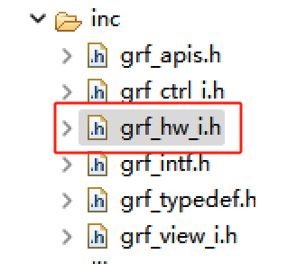
giraffe hardware-related API interfaces are in the grf_hw_i.h file. You can find it from the inc folder after creating the project.
This document describes how to use the relevant API in this folder, which is widely used in real project. I hope readers could study it carefully.
For the specific hardware interfaces supported by the product, please refer to the product specification.
Giraffe's extant hardware functions include
LCD,Touch,UART,WDT,GPIO,RTC,FLASH,SPI,IIC,PWMHardware files can be generated directly within the project
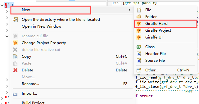
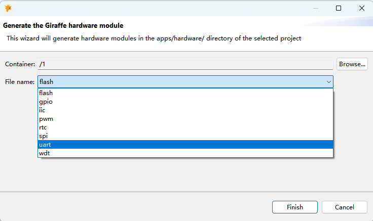
- After the hardware file is added, it will be called in the
grf_hw.cinitialisation function:
#include "grf_hw.h"

void grf_hw_init(void)
{
	grf_pwm_test();

	grf_iic_test();

	grf_spi_test();

	grf_rtc_test();

	grf_gpio_test();

    grf_uart_init();

    grf_wdt_task_create();
}
1. LCD Related Function
1.1 Set the screen brightness
s32 grf_disp_set_bright(u8 bright);bright: screen brightness ( brightness level 0-99, 99 is the brightest, 0 is the darkest. )
return : GRF_OK for success and GRF_FAIL for failure
This interface is usually used with the slider control to adjust the brightness of the screen.
2. Touch Related Function
typedef struct
{
    grf_touch_state t_state;
    u16 touch_x;
    u16 touch_y;
}grf_touch_t;
Touch struct, which includes the (x,y) coordinate value of the touch point and the touch state. Touch states include release and press. The enumeration is as follows:
typedef enum
{
    GRF_TOUCH_UP,
    GRF_TOUCH_DOWN
}grf_touch_state;
2.1 Get Touch
s32 grf_touch_get(grf_touch_t *_touch_t);_touch_t: the touch object pointer user wants to get
return: GRF_OK for success and GRF_FAIL for failure
You need to create a touch object before using the API, and the touch parameter can then be retrieved.
Routine:
This routine demonstrates how to get the touch coordinates and touch state, and display the information in different labels as text. The acquired touch coordinates are assigned to the mouse image, and the mouse moves accordingly.
The specific code is as follows. The code uses a task system to get the touch in real time. The usage of the task system is described in the Giraffe IDE API Usage Instruction, specifically located in Chapter 6, Timer Task System. And it will not be repeated here. The specific use should be decided by the user according to the actual situation.
void touch_task(grf_task_t *task_t)
{
	grf_touch_t touch_t = {0};
	grf_touch_get(&touch_t);
	u8 touchbuf[10] = {0};
	sprintf(touchbuf,"(%d,%d)",touch_t.touch_x,touch_t.touch_y);
	grf_ctrl_t* touch_label0 = grf_ctrl_get_form_id(GRF_VIEW1_ID,VIEW1_LABEL0_ID);
	grf_label_set_txt(touch_label0,touchbuf);
	grf_ctrl_t* touch_label3 = grf_ctrl_get_form_id(GRF_VIEW1_ID,VIEW1_LABEL3_ID);
	if(touch_t.t_state == GRF_TOUCH_UP){
		grf_label_set_txt(touch_label3,"up");
	}else{
		grf_label_set_txt(touch_label3,"down");
	}
	grf_ctrl_t* img = grf_ctrl_get_form_id(GRF_VIEW1_ID,VIEW1_IMAGE0_ID);
	grf_ctrl_set_pos(img,touch_t.touch_x,touch_t.touch_y);
}

void view_create_time_task(void)
{
	grf_task_create(touch_task,10,NULL);
}
3. UART Related Function
3.1 Open Serial Port
grf_drv_t* grf_drv_uart_open(grf_uart_cfg_t cfg_t);cfg_t: serial port object to be opened
return: device handle
The serial port parameter structure is as follows:
typedef struct
{
    s32 win_port;                  //PC port number
    s32 port;                      //serial port number. -1 is the default port
    grf_uart_speed_e speed_e;      //baud
    grf_uart_bit_e bit_e;          //data bit
    grf_uart_parity_e parity_e;    //parity bit
    grf_uart_stop_e stop_e;        //stop bit
}grf_uart_cfg_t;
The relevant enumerations are listed below:
typedef enum{
    UART_SPEED_2400,
    UART_SPEED_4800,
    UART_SPEED_9600,
    UART_SPEED_19200,
    UART_SPEED_38400,
    UART_SPEED_57600,
    UART_SPEED_115200,
    UART_SPEED_230400,
    UART_SPEED_460800,
    UART_SPEED_500000,
    UART_SPEED_576000,
    UART_SPEED_921600
}grf_uart_speed_e;
typedef enum{
    UART_BIT_7,
    UART_BIT_8
}grf_uart_bit_e;
typedef enum{
    UART_PARITY_NONE,
    UART_PARITY_ODD,
    UART_PARITY_EVEN
}grf_uart_parity_e;
typedef enum{
    UART_STOP_1,
    UART_STOP_2
}grf_uart_stop_e;
3.2 Shutdown Serial Port
s32 grf_drv_uart_close(grf_drv_t *drv_t);drv_t: device handle
return: GRF_OK for success and GRF_FAIL for failure
3.3 Serial Port Sending
s32 grf_drv_uart_send(grf_drv_t *drv_t,char* databuf, int datalen);drv_t: device handle
databuf: data address to be sent
datalen: data length to be sent
return : GRF_OK for success and GRF_FAIL for failure
3.4 Serial Port Receive Interrupt
3.4.1 Serial Port Receive Interrupt Service Function
typedef void (*uart_rev_bfun)(u8* databuf,u32 datalen);databuf: address for receiving data
datalen: length of received data
return: none
Serial port receive interrupt service function is used to write the processing logic of serial port receive interrupt.
3.4.2 Enable Serial Port Receive Interrupt Service Function
s32 grf_drv_uart_rev_set_bfun(grf_drv_t *drv_t,uart_rev_bfun rev_bfun,u32 max_len);drv_t: device handle
rev_bfun: serial port receive interrupt service function
max_len: Maximum value of data received at one time
return: GRF_OK for success and GRF_FAIL for failure
In the Giraffe IDE, the serial port related functions have been written in full. Users can add these functions by creating a new giraffe hardware file from the host project engineering. The added hardware file includes the serial port part and watchdog part of the code, which can be directly called by the user.
After adding it just open the grf_uart_init() function in the grf_hw_init() hardware initialization function. Serial port related parameters need to be set in the serial port initialization function. The port number defaults to 3, which can be modified according to your own device hardware.
Once the serial port is initialized, you need to set the address, key value and other information of the corresponding registers according to the protocol you defined. The relevant receive logic is then written in the grf_reg_set_user function.
Add the serial port related code as follows:
#include "../grf_hw.h"
#if GRF_HW_ENABLE
#include "grf_hw_uart.h"

static grf_drv_t *drv_uart = NULL;

//user code:user-written serial port logic functions
//addr:register address
//data:register data. The data is fetched sequentially from the first address.
//datalen:length of received data
void grf_reg_set_user(u16 addr,u16* data,u8 datalen)
{
    //user code

}


#define HEAD_FH 0x5A
#define HEAD_FL 0xA5
#define REG_LEN 0x800
static u16 ctrlreg[REG_LEN] = {0};

//Set register data
//addr:register address to be set
//data:data to be set
s32 grf_reg_set(u16 addr,u16 data)
{
    if(addr>REG_LEN){
        return GRF_FAIL;
    }
    ctrlreg[addr] = data;
    // grf_printf("set reg %04X = %04X\n",addr,data);
    return GRF_OK;
}

//Get the register data
//addr:register address to be fetched
s32 grf_reg_get(u16 addr)
{
    if(addr>REG_LEN){
        return GRF_FAIL;
    }
    // grf_printf("get reg %04X = %04X\n",addr,ctrlreg[addr]);
    return ctrlreg[addr];
}
//*********write reg**********
//TX - FH FL len cmd addr data0 data1
//     5A A5 07  82  0001 FFFF  FFFF
//RX - NULL

//*********read reg**********
//TX -  FH FL len cmd addr reglen
//      5A A5 04  83  0001  02
//RX -  FH FL len cmd addr reglen data0 data1
//      5A A5 08  83  0001  02    FFFF  FFFF

static s32 grf_reg_s_set(u16 addr,u8* data,u8 len)
{
    if(addr>REG_LEN){
        return GRF_FAIL;
    }
    u8 i=0;
    for(i=0;i<len;i++){
        ctrlreg[addr+i] = (data[i*2]<<8)+data[i*2+1];
        // grf_printf("reg_s_set %04X = %04X\n",addr+i,ctrlreg[addr+i]);
        grf_reg_set_user(addr,ctrlreg+addr+i,1);
    }
    return GRF_OK;
}

//Register send-function
//addr:register address to be sent
//len:data length to be sent
s32 grf_reg_com_send(u16 addr,u16 len)
{
    u8 txdata[257] = {0};
    u32 i=0,j=0;
    txdata[i++] = HEAD_FH;
    txdata[i++] = HEAD_FL;
    txdata[i++] = len*2+4;
    txdata[i++] = 0x83;
    txdata[i++] = addr>>8;
    txdata[i++] = (addr&0x00ff);
    txdata[i++] = len;
    for(j=0;j<len;j++){
        txdata[i++] = (ctrlreg[addr+j]>>8);
        txdata[i++] = (ctrlreg[addr+j]&0x00ff);
    }
    grf_drv_uart_send(drv_uart,txdata,i);
}

//Instruction parsing function
static s32 grf_comm_handle(u8* data)
{
	u8 cmd = data[3];
	u8 len = data[2];
    u16 addr = (data[4]<<8)+data[5];
    u32 i=0;
    if(addr>REG_LEN){
        return GRF_FAIL;
    }
    //    grf_printf("cmd=%x\n",cmd);
    switch (cmd)
    {
        case 0x82: //write registers
        {
            u32 regcount = (len-3)>>1;
            grf_reg_s_set(addr,data+6,regcount);
        }
        break;
        case 0x83: //read registers
        	grf_reg_com_send(addr,data[6]);
        break;
    }
    return GRF_OK;
}

#define UART_LASTBUFF 1
#if UART_LASTBUFF
#define RX_BUF_LEN   1024
static u8 RX_HAND_BUF[RX_BUF_LEN];
#endif

//Serial port receive interrupt service function
//databuf:received data
//datalen:length of received data
static void recive_data_handle(u8* databuf,u32 datalen)
{
	u16 i=0;
	static u16 last_data_num=0;
#if UART_LASTBUFF
	if(last_data_num + datalen > RX_BUF_LEN){
		datalen = datalen-last_data_num;
	}
	if(last_data_num){
		memcpy(RX_HAND_BUF+last_data_num,databuf,datalen);
		databuf=RX_HAND_BUF;
		datalen+=last_data_num;
		last_data_num = 0;
	}
#endif
#if 1
    grf_printf("uart rx[%d]:",datalen);
	for(i=0;i<datalen;i++){
		grf_printf(" %02X",databuf[i]);
	}
	grf_printf("\n",datalen);
#endif
	if(datalen>=6){//Shortest command consists of 6 characters
		for(i=0;i<=datalen-6;i++)
        {
			if((databuf[i]==HEAD_FH) && (databuf[i+1]==HEAD_FL))
			{
    			if(databuf[i+2] <= (datalen-i-3)){
                    if(grf_comm_handle(databuf+i)==GRF_OK){
                        i += (databuf[i+2]+3)-1;
                    }
    			}
		        else{
                    last_data_num = datalen-i;
                    break;
		        }
			}
		}
	}
	else{
		last_data_num = datalen;
	}
#if UART_LASTBUFF
	if(last_data_num<=256 && last_data_num!=0)
	{
		u8  last_data_buf[256] = {0};
		memcpy(last_data_buf,databuf+i,last_data_num);
		memcpy(RX_HAND_BUF,last_data_buf,last_data_num);
	}else{
		last_data_num=0;
	}
#else
	last_data_num = 0;
#endif
}

//Port initialization functions
void grf_uart_init(void)
{
    grf_uart_cfg_t cfg_t = {0};
    cfg_t.port = 3;//IC port number
    cfg_t.win_port = 2;//PC port number
    cfg_t.speed_e = UART_SPEED_115200;
    cfg_t.bit_e = UART_BIT_8;
    cfg_t.parity_e = UART_PARITY_NONE;
    cfg_t.stop_e = UART_STOP_1;
    drv_uart = grf_drv_uart_open(cfg_t);
    if(drv_uart){
        grf_drv_uart_rev_set_bfun(drv_uart,recive_data_handle,1024);
    }
}
4. WDT Related Function
Watchdog Related Functions. Users can add these functions by creating a new giraffe hardware file from the host project engineering. Added hardware file includes the serial port part and the watchdog part of the code, which can be used after openning the corresponding initialization function.
4.1 Turn on the Watchdog
s32 grf_wdt_open(void);return: GRF_OK for success and GRF_FAIL for failure
4.2 Turn off the Watchdog
s32 grf_wdt_close(void);return: GRF_OK for success and GRF_FAIL for failure
4.3 Set Watchdog Timeout Time
s32 grf_wdt_set_timeout(u32 time);time: timeout time, unit of seconds
return: GRF_OK for success and GRF_FAIL for failure
4.4 Refresh Watchdog Time
s32 grf_wdt_keepalive(void);return: GRF_OK for success and GRF_FAIL for failure
The code for adding the watchdog hardware file is as follows:
#include "../grf_hw.h"
#if GRF_HW_ENABLE
#include "grf_hw_wdt.h"

void grf_wdt_task_cb(grf_task_t *task_t)
{
    grf_wdt_keepalive();
}

grf_task_t *wdt_task_t = NULL;
void grf_wdt_task_create(void)
{
    if(wdt_task_t==NULL){
        wdt_task_t = grf_task_create(grf_wdt_task_cb,500,NULL);
        grf_wdt_set_timeout(5);
        grf_wdt_open();
    }
}

#endif
The watchdog task is executed with a period of 500ms, i.e., refresh the watchdog once in 500ms. Timeout time is 5s, once the anomaly exceeds 5s the system automatically reboot.
The code after the addition has been written, user can use the watchdog task inside the grf_hw.c initialization function directly by turning it on. The details are as follows:
#include "grf_hw.h"
void grf_hw_init(void)
{
	grf_wdt_task_create();
}
5.GPIO Related Function
5.1 GPIO Initialization Function
s32 grf_gpio_init(grf_gpio_para_t* para_t);para_t: gpio structure variables to be initialized
return: GRF_OK for success and GRF_FAIL for failure
5.2 Set the GPIO Pins
s32 grf_gpio_setPin(u8 gpio_group,u8 gpio_pin,u8 value);gpio_group: gpio port
gpio_pin: gpio pin
value: pin level, 0: low level 1: high level
return: GRF_OK for success and GRF_FAIL for failure
5.3 Get Input Pin Level
s32 grf_gpio_readInputPin(u8 gpio_group,u8 gpio_pin);gpio_group: gpio port
gpio_pin: gpio pin
return: return the acquired pin level for success, GRF_FAIL for failure
5.4 Get Output Pin Level
s32 grf_gpio_readOutputPin(u8 gpio_group,u8 gpio_pin);gpio_group: gpio port
gpio_pin: gpio pin
return: return the acquired pin level for success, and GRF_FAIL for failure
5.5 Set GPIO Interrupt
s32 grf_gpio_group_set_irq(grf_gpio_irq_para_t irq_para_t);irq_para_t: interrupt structure variable to be configured
return: GRF_OK for success and GRF_FAIL for failure
5.6 Get Interrupt Pin
s32 grf_gpio_group_get_irq_pin(grf_gpio_irq_t *irq_t);irq_t: interrupt structure variable
return: return the obtained gpio pin number for success, and GRF_FAIL for failure
5.7 Get Interrupt Mode
s32 grf_gpio_group_get_irq_mode(grf_gpio_irq_t *irq_t);irq_t: interrupt structure variable
return: return the obtained gpio interrupt mode for success, and GRF_FAIL for failure
The code for adding the GPIO is as follows:
#include "../grf_hw.h"
#if GRF_HW_ENABLE
#include "grf_hw_gpio.h"
Routine:
Configuration:
void gpio_set_data_test(void)
{
    grf_gpio_para_t gpio_para = {0};
    gpio_para.gpio_group = GRF_GPIO_GROUP_E;
    gpio_para.gpio_pin = 18;
    gpio_para.gpio_mode = GRF_GPIO_OUTPUT;
    grf_gpio_init(&gpio_para);

    while (1)
    {
        grf_gpio_setPin(GRF_GPIO_GROUP_E,18,1);
        grf_printf("set pin 1\n");
        grf_delay(500);

        grf_gpio_setPin(GRF_GPIO_GROUP_E,18,0);
        grf_printf("set pin 0\n");
        grf_delay(500);
    }
}
Read:
void gpio_set_data_test(void)
{
    grf_gpio_para_t gpio_para = {0};
    gpio_para.gpio_group = GRF_GPIO_GROUP_E;
    gpio_para.gpio_pin = 18;
    gpio_para.gpio_mode = GRF_GPIO_OUTPUT;
    grf_gpio_init(&gpio_para);

    while (1)
    {
        grf_gpio_setPin(GRF_GPIO_GROUP_E,18,1);
        grf_printf("set pin 1\n");
        grf_delay(500);

        grf_gpio_setPin(GRF_GPIO_GROUP_E,18,0);
        grf_printf("set pin 0\n");
        grf_delay(500);
    }
}
Key interrupt routine:
typedef enum {
    KEY_UP,
    KEY_DOWN,

    KEY_DOWN_LONG,
    KEY_NO
}key_state_e;
typedef struct
{
    key_state_e key_state;
    u32 key_time;

    key_state_e last_key_state;
}key_param_t;
key_param_t key_para[2] = {0};
void irq_task_test1(grf_gpio_irq_t *irq_t)
{
    u8 irq_pin = grf_gpio_group_get_irq_pin(irq_t);
    u8 irq_mode = grf_gpio_group_get_irq_mode(irq_t);
    // grf_printf("irq_pin = %d irq_mode=%d \n",irq_pin,irq_mode);
    switch (irq_pin)
    {
        case 0://PE 0 IRQ interrupt
            if(irq_mode == GRF_GPIO_IRQ_RISING){
                key_para[0].key_state = KEY_DOWN;
                key_para[0].key_time = grf_sys_time_ms();
            }
            else{
                key_para[0].key_state = KEY_UP;
                key_para[0].key_time = grf_sys_time_ms();
            }
        break;
        case 1://PE 1 IRQ interrupt
            if(irq_mode == GRF_GPIO_IRQ_RISING){
                key_para[1].key_state = KEY_DOWN;
                key_para[1].key_time = grf_sys_time_ms();
            }
            else{
                key_para[1].key_state = KEY_UP;
                key_para[1].key_time = grf_sys_time_ms();
            }
        break;

    default:
        break;
    }
}
static key_state_e key_get_state(key_param_t *key_para)
{
    key_state_e state_e = KEY_NO;
    if(key_para->key_state == KEY_DOWN){
        u32 cur_time = grf_sys_time_ms();
        u32 key_time = key_para->key_time;
        if(cur_time>key_time && cur_time-key_time>10){ //10ms jitter
            key_para->last_key_state = KEY_DOWN;
            state_e = KEY_DOWN;
            if(cur_time-key_time>2000){//2s long press
                state_e = KEY_DOWN_LONG;
            }
        }
    }
    else{
        if(key_para->key_state == KEY_UP && key_para->last_key_state == KEY_DOWN){
            state_e = KEY_UP;
            key_para->last_key_state = KEY_UP;
        }
    }
    return state_e;
}
static void irq_task_cb_t(grf_task_t *task_t)
{
    key_state_e state_e = key_get_state(&key_para[0]);
    if(state_e!=KEY_NO){
        grf_printf("KEY 0 state_e=%d \n",state_e);
    }
    state_e = key_get_state(&key_para[1]);
    if(state_e!=KEY_NO){
        grf_printf("KEY 1 state_e=%d \n",state_e);
    }
}

void gpio_irq_test(void)
{
    grf_gpio_irq_para_t irq_para_t = {0};
    u8 pins[2] = {0,1};//PE0,PE1
    irq_para_t.irq_group = GRF_GPIO_GROUP_E;
    irq_para_t.irq_pins = pins;
    irq_para_t.gpio_pin_num = 2;
    irq_para_t.mode_e = GRF_GPIO_IRQ_RISING_FALLING;//rising edge interrupt
    irq_para_t.irq_task = irq_task_test1;
    s32 ret = grf_gpio_group_set_irq(irq_para_t);
    grf_printf("ret=%d\n",ret);

    grf_task_create(irq_task_cb_t, 10,NULL);
}

void grf_gpio_test(u8 cmd)
{
    switch (cmd)
    {
        case SET_GPIO_TEST:
            gpio_set_data_test();
            break;
        case GET_GPIO_TEST:
            gpio_get_data_test();
            break;
        case GPIO_IRQ_TEST:
            gpio_irq_test();
            break;
        default:
            break;
    }

}6.RTC Related Function
6.1 Set the RTC
s32 grf_rtc_set_time(grf_rtc_time_t* rtc_t);rtc_t: RTC structure variable
return: GRF_OK for success and GRF_FAIL for failure
6.2 Get RTC
s32 grf_rtc_get_time(grf_rtc_time_t* rtc_t);rtc_t: RTC structure variable
return: GRF_OK for success and GRF_FAIL for failure
The structure variable is as follows:
typedef  struct
{
    u16 year;//year
    u8 month;//month
    u8 day;//day
    u8 hour;//hour
    u8 minute;//minute
    u8 second;//second
}grf_rtc_time_t;
The code for adding the RTC is as follows:
#include "../grf_hw.h"
#if GRF_HW_ENABLE
#include "grf_hw_rtc.h"

//Get the time
static void get_rtc_time(void)
{
    grf_rtc_time_t rtc_t = {0};
    grf_rtc_get_time(&rtc_t);
    grf_printf("get y=%d m=%d d=%d h=%d m=%d s=%d \n",rtc_t.year,rtc_t.month,rtc_t.day,rtc_t.hour,rtc_t.minute,rtc_t.second);
}

//Set the time
void set_rtc_time(void)
{
    grf_rtc_time_t rtc_t = {0};
    rtc_t.year = 2023;      //year
    rtc_t.month = 4;        //month
    rtc_t.day = 5;          //day
    rtc_t.hour = 6;         //hour
    rtc_t.minute = 7;       //minute
    rtc_t.second = 8;       //second
    grf_rtc_set_time(&rtc_t);
    grf_printf("set y=%d m=%d d=%d h=%d m=%d s=%d \n",rtc_t.year,rtc_t.month,rtc_t.day,rtc_t.hour,rtc_t.minute,rtc_t.second);
}

void grf_rtc_test_task_cb(grf_task_t *task_t)
{
    get_rtc_time();
}

void grf_rtc_test(void)
{
    get_rtc_time();
    grf_delay(500);
    set_rtc_time();
    grf_task_create(grf_rtc_test_task_cb,500,NULL);
}


#endif
7. FLASH Related Function
7.1 Get Flash File Path
u8 *grf_dir_get_ddisk();return: return the path to the obtained file
7.2 Get TF Card File Path
u8 *grf_dir_get_tfdisk();return: return the path to the obtained file
7.3 Get the Path to a USB Flash Disk File
u8 *grf_dir_get_udisk();return: return the path to the obtained file
The code for adding the FLASH is as follows:
#include "../grf_hw.h"
#if GRF_HW_ENABLE
#include "grf_hw_flash.h"

#define BINFILE   "grf_data.bin"

//string splicing
s32 ConnectStr(char * dest,int len, const char * str1, const char * str2)
{
	if (!dest || len < 1) return GRF_FAIL;
	int pos = 0;
	memset(dest,0,len);
	strcat(dest,str1);
	strcat(dest,str2);
	return GRF_OK;
}

/*
*Function: u32 grf_flash_write_Data(__u8 type,u32 addr,__u8* databuf,u32 len)
*Description: write data to flash(grf_data.bin)
*Formal parameter:
	type - Storage device type,0: flash 1: TF card 2: U disk
	addr - Write first address of data (0-0xFFFFFFFF)
	databuf - Data buffer to be stored for writing
	len - Write data length in bytes
*Return: Number of bytes actually read
*/
u32 flash_write_Data(u8 type,u32 addr,u8* databuf,u32 len)
{
    char wfilename[256] = {0};
	u8* pathtype = NULL;
	s8 ret = 0;
	u32 reallen = 0;

	//Select a path
	if(type==1){
        pathtype = grf_dir_get_ddisk();
        ConnectStr(wfilename,256,pathtype,BINFILE);
	}
	else if(type==2){
        pathtype = grf_dir_get_tfdisk();
        ConnectStr(wfilename,256,pathtype,BINFILE);
	}
	else{
        pathtype = grf_dir_get_udisk();
        ConnectStr(wfilename,256,pathtype,BINFILE);
	}
	// grf_printf("wfilename=%s\n",wfilename);
	if(wfilename[0]!=0)
	{
		FILE*   datafp=NULL;
		datafp = fopen(wfilename,"r+b");
		if(datafp == NULL){
        //First think that the file has not been created
			datafp = fopen(wfilename,"wb");
		}
		if(datafp==NULL)
		{
			printf("create grf_data.bin fail\n");
			fclose(datafp);
	        goto __err;
		}
		ret = fseek(datafp,addr,SEEK_SET);
		//grf_printf("ret=%d\n",ret);
		if(ret!=0){//If the address to be written exceeds the total size of the file, first expand the file with 0, and then write the data.
			u32 endlen,offset;
			void *data_p;
			fseek(datafp,0,SEEK_END);
			endlen = ftell(datafp);
			offset = addr-endlen;
			data_p = malloc(offset);
			memset(data_p,0, offset);
			fwrite(data_p,1,offset,datafp);
			free(data_p);
			//grf_printf("endlen=%d offset=%d \n",endlen,offset);
		}
		reallen = fwrite(databuf,1,len,datafp);
		fclose(datafp);
	}
__err:
	return reallen;
}

/*
*Function: u32 grf_flash_read_Data(__u8 type,u32 addr,__u8* databuf,u32 len)
*Description: read data from flash(grf_data.bin)
*Formal parameter:
	type - Storage device type,0: flash 1: TF card 2: U disk
	addr - Read first address of data (0-0xFFFFFFFF)
	databuf - Data buffer to be stored for reading
	len - Read data length in bytes
*Return: Number of bytes actually write
*/
u32 flash_read_Data(u8 type,u32 addr,u8* databuf,u32 len)
{
    char rfilename[256];
	s8 ret = 0;
	u32 reallen = 0;
    memset(rfilename,0,256);
	//Select a path
	if(type==1){
        u8* pathtype = grf_dir_get_ddisk();
        ConnectStr(rfilename,64,pathtype,BINFILE);
	}
	else if(type==2){
        u8* pathtype = grf_dir_get_tfdisk();
        ConnectStr(rfilename,64,pathtype,BINFILE);
	}
	else{
        u8* pathtype = grf_dir_get_udisk();
        ConnectStr(rfilename,64,pathtype,BINFILE);
	}
	// grf_printf("rfilename=%s\n",rfilename);
	{
		FILE*   datafp=NULL;
		datafp = fopen(rfilename,"rb");
		if(datafp==NULL)
		{
			grf_printf("open grf_data.bin fail\n");
			fclose(datafp);
	        goto __err;
		}
		ret =fseek(datafp,addr,SEEK_SET);
		if(ret==0){//Addressing success
			reallen = fread(databuf,1,len,datafp);
		}
		else{
			grf_printf("The location exceeds the file size,addr=0x%04x\n",addr);
		}
		fclose(datafp);
	}
__err:
	return reallen;
}

#endif
8. SPI Related Function
8.1 SPI Open
grf_drv_t* grf_spi_open(grf_spi_para_t *para_t);para_t: SPI structure variable to be opened
return: device handle
The SPI structure is as follows:
typedef struct
{
    u32   port;      //port number
	u32	  work_clk;  //Bus rate, unit: HZ
  	u32   work_mode; //SPI operating mode
	u8	  nbits;     //bit number
  	u16	  delay;     //send interval
}grf_spi_para_t;work_mode:
#define SPI_WORK_MODE0 (0|0) //Sample on rising edge, send on falling edge
#define SPI_WORK_MODE1 (0|SPI_CPHA) //Send on rising edge, sample on falling edge
#define SPI_WORK_MODE2 (SPI_CPOL|0) //Send on rising edge, sample on falling edge
#define SPI_WORK_MODE3 (SPI_CPOL|SPI_CPHA) //Sample on rising edge, send on falling edge8.2 SPI Transmission Interface
s32 grf_spi_transfer(grf_drv_t* drv_t,u8 *tx,u32 tx_len,u8 *rx,u32 rx_len);drv_t: device handle
tx: data transmit buffer address
tx_len: the length of transmited data
rx: data receive buffer address
len: the length of received data
return: GRF_OK for success and GRF_FAIL for failure
8.3 SPI Shutdown
s32 grf_spi_close(grf_drv_t *drv_t);drv_t: device handle
return: GRF_OK for success and GRF_FAIL for failure
The code for adding the SPI is as follows:
#include "../grf_hw.h"
#if GRF_HW_ENABLE
#include "grf_hw_spi.h"
static grf_drv_t *drv_spi = NULL;
void grf_spi_test(void)
{
grf_spi_para_t para_t;
u8 tx_buf[10] = {0,1,2,3,4,5,6,7,8,9};
u8 rx_buf[10] ={0};
int i=0;
para_t.port = 1;
para_t.work_mode = SPI_WORK_MODE3;
para_t.work_clk = 50*100*100;
para_t.nbits = 8;
para_t.delay = 0;
drv_spi = grf_spi_open(¶_t);
grf_spi_transfer(drv_spi,tx_buf,10,rx_buf,10);
for(i=0;i<sizeof(tx_buf);i++){
grf_printf("readdata[%d]=%x\n", i,rx_buf[i]);
}
}
#endif9. IIC Related Function
9.1 IIC Open
grf_drv_t* grf_iic_open(grf_iic_para_t* para_t);para_t: IIC structure variable to be opened
return: device handle
The IIC structure is as follows:
typedef struct
{
    u32     port;            //port number
    u8      slave_addr;      //device address
    u8      reg_addr;        //register address
    u8      reg_addr_width;  //number of register bytes
}grf_iic_para_t;
9.2 IIC Read Data
s32 grf_iic_read(grf_drv_t* drv_t,u16 addr,u8 *buff,u16 len);drv_t: device handle
addr: address of the device to be read
buff: receive data buffer
len: length of the recieved data
return: number of bytes actually read
9.3 IIC Write Data
s32 grf_iic_write(grf_drv_t* drv_t,u16 addr,u8 *buff,u16 len);drv_t: device handle
addr: address of the device to be written
buff: transmit data buffer
len: length of the sent data
return: number of bytes actually written
9.4 IIC Shutdown
s32 grf_iic_close(grf_drv_t *drv_t);drv_t: device handle
return: GRF_OK for success and GRF_FAIL for failure
The code for adding the IIC is as follows:
#include "../grf_hw.h"
#if GRF_HW_ENABLE
#include "grf_hw_iic.h"
static grf_drv_t *drv_iic = NULL;
grf_task_t *iic_rtc_task = NULL;
u8 bcd_to_dec(u8 bcd)
{
bcd = bcd & 0x7f;
return ((bcd & 0xF0) >> 4) * 10 + (bcd & 0x0F);
}
u8 dec_to_bcd(u8 dec) {
return ((dec / 10) << 4) | (dec % 10);
}
void iic_rtc_task_cb(grf_task_t *task_t)
{
u8 rbuff[10]={0};
grf_iic_read(drv_iic,0x02,rbuff,10);
u8 second = bcd_to_dec(rbuff[0]);
u8 minute = bcd_to_dec(rbuff[1]);
u8 hour = bcd_to_dec(rbuff[2]);
u8 day = bcd_to_dec(rbuff[3]);
u8 month = bcd_to_dec(rbuff[5]);
u8 year = bcd_to_dec(rbuff[6]);
grf_printf("iic rtc time = %04d/%02d/%02d %02d:%02d:%02d \n",year+2000,month,day,hour,minute,second);
}
static void iic_rtc_set(void)
{
u8 rbuff[10]={0};
rbuff[0] = dec_to_bcd(10); //second
rbuff[1] = dec_to_bcd(13); //minute
rbuff[2] = dec_to_bcd(17); //hour
rbuff[3] = dec_to_bcd(30); //day
rbuff[5] = dec_to_bcd(5); //month
rbuff[6] = dec_to_bcd(2024-2000); //year
grf_iic_write(drv_iic,0x02,rbuff,7);
}
void grf_iic_test(void)
{
if(iic_rtc_task == NULL){
grf_iic_para_t para_t={0};
para_t.port=0;
para_t.slave_addr =0x51;
para_t.reg_addr_width=1;
drv_iic = grf_iic_open(¶_t);
iic_rtc_set();
iic_rtc_task = grf_task_create(iic_rtc_task_cb,500,NULL);
}
}
#endif10. PWM Related Function
10.1 PWM Open
grf_drv_t* grf_pwm_open(grf_pwm_para_t* para_t);para_t: PWM structure variable to be opened
return: device handle
The PWM structure is as follows:
typedef struct
{
    u32     channel;        //pwm channel
    u32     period_time;    //period unit: ns
    u32     pulse_time;     //pulse time unit: ns
}grf_pwm_para_t;
10.2 PWM Startup
s32 grf_pwm_start(grf_drv_t *drv_t);drv_t: device handle
return: GRF_OK for success and GRF_FAIL for failure
10.3 PWM Setting
s32 grf_pwm_set(grf_drv_t *drv_t,u32 period_time,u32 pulse_time);drv_t: device handle
period_time: period of PWM
pulse_time: pulse width
return: GRF_OK for success and GRF_FAIL for failure
10.4 PWM Stop
s32 grf_pwm_stop(grf_drv_t *drv_t);drv_t: device handle
return: GRF_OK for success and GRF_FAIL for failure
10.5 PWM Shutdown
s32 grf_pwm_close(grf_drv_t *drv_t);drv_t: device handle
return: GRF_OK for success and GRF_FAIL for failure
The code for adding the PWM is as follows:
#include "../grf_hw.h"
#if GRF_HW_ENABLE
#include "grf_hw_pwm.h"
static grf_drv_t* pwm_drv = NULL;
grf_task_t *pwm_task_t = NULL;
void grf_pwm_task_cb(grf_task_t *task_t)
{
static u8 flag = 0;
static u8 value = 0;
if(!flag){
value+=2;
if(value >= 100){
flag = 1;
}
}
else{
value-=2;
if(value == 0){
flag = 0;
}
}
grf_printf("pwm=%d\n",value);
grf_pwm_set(pwm_drv,1000,10*value);
}
void grf_pwm_test(void)
{
if(pwm_task_t==NULL){
grf_pwm_para_t para_t;
para_t.channel = 1;
para_t.period_time = 1000;
para_t.pulse_time = 0;
pwm_drv = grf_pwm_open(¶_t);
grf_pwm_start(pwm_drv);
pwm_task_t = grf_task_create(grf_pwm_task_cb,10,NULL);
}
}
#endif11. Network Usage Instruction
This chapter mainly explains how to adapt the network driver in Giraffe, Giraffe currently only adapts Ethernet and WIFi on the hardware, only HTTP and MQTT on the application layer protocols; other application layer protocols and Bluetooth hardware will be gradually improved later.
11.1 Add Network Library (IDE 1.2.10 and above)
Firmware version: after August 2024
TR660 Linux board with Ethernet/WIFI support
Giraffe SDK version: 1.2.10 and above
Source link: Download
11.1.1 Copy Dynamic Library Driver
Copy the tr6_libs folder and init.d folder to the res folder of the Giraffe project
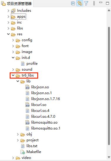
Copy the files in the lib folder again into the Giraffe installation directory ~/platform/tr660/usr/lib/(the lib folder is located in the tr6_libs folder)
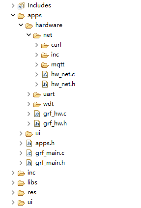
11.1.2 Copy Hardware Parameters API Functions
- Copy the
netfolder to the apps/hardware/ directory of your Giraffe project
- Modify the apps/hardware/grf_hw.h header file to add the header file include
Modified:
#ifndef __GRF_HW_H_
#define __GRF_HW_H_


#include "../../inc/grf_apis.h"
#define GRF_HW_ENABLE  1


//The following .h is automatically added
#include "../apps.h"
#include "uart/grf_hw_uart.h"
#include "wdt/grf_hw_wdt.h"
#include "net/hw_net.h"


void grf_hw_init(void);

#endif- Modify apps/hardware/net/hw_net.h
Modify the included header files according to compilation needs.
These files are: iperf.h, curl.h, matt.h
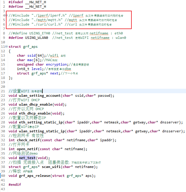
At this point, the network compilation environment has been built successfully(Giraffe SDK version 1.2.10 and above do not require modifying compilation options)
11.2 Add Network Library (IDE 1.2.10 below)
Firmware version: after August 2024
TR660 Linux board with Ethernet/WIFI support
Giraffe SDK version: below 1.2.10
Source link: http://download.giraffeide.com/net-server/net.zip
11.2.1 Copy Dynamic Library Driver
Copy the lib folder and init.d folder into the res folder of your Giraffe project
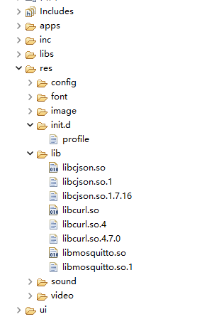
Copy the files in the lib folder again into the Giraffe installation directory ~/platform/tr660/usr/lib/
11.2.2 Copy Hardware Parameters API Functions
- Copy the
netfolder to the apps/hardware/ directory of your Giraffe project
- Modify the apps/hardware/grf_hw.h header file to add the header file include
Modified:
#ifndef __GRF_HW_H_
#define __GRF_HW_H_


#include "../../inc/grf_apis.h"
#define GRF_HW_ENABLE  1


//The following .h is automatically added
#include "../apps.h"
#include "uart/grf_hw_uart.h"
#include "wdt/grf_hw_wdt.h"
#include "net/hw_net.h"


void grf_hw_init(void);

#endif- Modify apps/hardware/net/hw_net.h
Modify the included header files according to compilation needs.
These files are: iperf.h, curl.h, matt.h
11.2.3 Modify Compilation Options
- Modify ~/platform/tr660/Makefile in the Giraffe SDK installation directory
#Connection Library
#LIBFLAGS = -lgrfui -lmingw32 -lSDL2main -lSDL2 -lfreetype-6
LIBFLAGS = -ltr660grfui -lts -lm -lz -lfaad -lmad -lmpp_base -lmpp_decoder -lmpp_encoder -lmpp_ge -lmpp_ve -lopenmax_base -lopenmax -lmedia_player -lasound -lmpp_audio_decoder -lpthread -lfreetype
After adding -lssl -lmosquitto -lcrypto -lcurl:
#Connection Library
#LIBFLAGS = -lgrfui -lmingw32 -lSDL2main -lSDL2 -lfreetype-6
LIBFLAGS = -ltr660grfui -lts -lm -lz -lfaad -lmad -lmpp_base -lmpp_decoder -lmpp_encoder -lmpp_ge -lmpp_ve -lopenmax_base -lopenmax -lmedia_player -lasound -lmpp_audio_decoder -lpthread -lfreetype -lssl -lmosquitto -lcrypto -lcurl
Note: After the Makefile modification, when compiling an ordinary TR660 project (i.e., a TR660 project where the screen hardware does not support networking), the network-related library files will be linked at this time as well, and when they are downloaded in, the project will not be able to run due to the lack of library files.
At this point, the network compilation environment has been built successfully, and you can compile mqtt and http code normally.
11.3. Wifi/Ethernet Parameter Configuration API Description
11.3.1 Ethernet Static IP Configuration Function
void eth_setting_static_ip(char* ipaddr,char* netmask,char* getway,char* dnsserver);ipaddr: IP address
netmask: subnet mask
getway: gateway address
dnsserver: DNS server address
return: NULL
11.3.2 Ethernet DHCP Enable Function
void eth_dhcp_enable(void);return: NULL
11.3.3 WIFI Account & Password Configuration Function
void wlan_setting_account(char* ssid,char* passwd);ssid: Wi-Fi account
passwd: Wi-Fi password
return: NULL
11.3.4 WIFI_DHCP Enable Function
void wlan_dhcp_enable(void);return: NULL
11.3.5 WIFI_Static IP Configuration Function
void wlan_setting_static_ip(char* ipaddr,char* netmask,char* getway,char* dnsserver);ipaddr: IP address
netmask: subnet mask
getway: gateway address
dnsserver: DNS server address
return: NULL
11.3.6 Network test demo
void net_test(void);Configure Wifi information when opening the macro definition USING_WLAN0.
Configure Ethernet information when opening the macro USING_ETH0.
11.3.7 Switch on NIC
int open_netif(const char* netifname);netifname : NIC Name
return: 0 success
11.3.8 Detecting the IP address of a network card
int check_netif(const char* netifname,char* ipaddr);netifname : NIC Name
ipaddr :IP address string
return: 0 success -1 fail
11.3.9 Scan for wireless access points
struct grf_aps* scan_wifi(char* netifname);netifname : NIC Name
return: AP Structure Chained Tables
11.3.10 Release the chained list of AP structure
void grf_aps_release(struct grf_aps* aps);return: NULL
11.4. MQTT/HTTP Usage Notes
11.4.1 Environment
TR660 Linux has already ported the CURL library to implement HTTP/TTPS protocol, and the MOSQUITTO library to implement MQTT protocol, so the Giraffe SDK can use the CURL standard API and the MOSQUITTO standard API normally.
CURL library version:

MOSQUITTO library version: 2.0.18
net/http implements the http/https standard get request demo net/mqtt implements the mqtt initialisation and message forwarding demo
For more detailed information, please refer to the CURL documentation and MOSQUITTO documentation.
12. CAN Related Function
12.1 CAN OPEN
grf_drv_t* grf_can_open(grf_can_cfg_t cfg_t);cfg_t: CAN object to be opened return: GRF_OK for success and GRF_FAIL for failure
CAN parameter structure is as follows:
typedef struct
{
    s32 port;                   // IC port number, -1 is the default port
    grf_can_speed_e speed_e;    // baud
    grf_can_filter *filter;     // filter
}grf_can_cfg_t;
The relevant enumerations are listed below:
typedef enum{
    CAN_SPEED_1M     = 1000UL * 1000,    /* 1 MBit/sec   */
    CAN_SPEED_800K   = 1000UL * 800,     /* 800 kBit/sec */
    CAN_SPEED_500K   = 1000UL * 500,     /* 500 kBit/sec */
    CAN_SPEED_250K   = 1000UL * 250,     /* 250 kBit/sec */
    CAN_SPEED_125K   = 1000UL * 125,     /* 125 kBit/sec */
    CAN_SPEED_100K   = 1000UL * 100,     /* 100 kBit/sec */
    CAN_SPEED_50K    = 1000UL * 50,      /* 50 kBit/sec  */
    CAN_SPEED_20K    = 1000UL * 20,      /* 20 kBit/sec  */
    CAN_SPEED_10K    = 1000UL * 10       /* 10 kBit/sec  */
}grf_can_speed_e;
typedef enum {
    CAN_FRAME_FORMAT_STD = 0,
    CAN_FRAME_FORMAT_EXT = 1,
}grf_can_frame_format_e;
typedef enum {
    CAN_FRAME_TYPE_DATA      = 0,
    CAN_FRAME_TYPE_REMOTE    = 1,
}grf_can_frame_type_e;
typedef struct
{
    u32 id;                         /* Message ID */
    u32 idmask;                     /* ID mask, 0 means the corresponding bit does not care, 1 means the corresponding bit must match */
    grf_can_frame_format_e ide;     /* Standard/Extended frames only*/
}grf_can_filter;//Only receive standard data frame with ID 0x100~0x1FF
cfg_t.filter->id = 0x100;
cfg_t.filter->ide = CAN_FRAME_FORMAT_STD;
cfg_t.filter->idmask = 0x700;12.2 CAN CLOSE
s32 grf_can_close(grf_drv_t *drv_t);drv_t: device Handle return: GRF_OK for success and GRF_FAIL for failure
12.3 CAN Transmit
s32 grf_can_send(grf_drv_t *drv_t,grf_can_msg_t *msg);drv_t: device Handle msg: message object return: GRF_OK for success and GRF_FAIL for failure
The CAN message structure is as follows:
typedef struct {
    u32 id;                      // ID
    grf_can_frame_type_e ide;    // Standard Frame / Extended Frame
    grf_can_frame_format_e rtr;  // Data frame / Remote frame
    u8 dlc;                      //data length
    u8 data[8];
}grf_can_msg_t;
12.4 CAN Receive Interrupt
12.4.1 CAN Receive Interrupt Service Function
typedef void (*can_rev_bfun)(grf_can_msg_t* msg_t);msg_t: message object return: none
CAN receive interrupt service function is used to write the processing logic for CAN receive interrupt.
12.4.2 Enable CAN Receive Interrupt Service Function
s32 grf_can_rev_set_bfun(grf_drv_t *drv_t,can_rev_bfun rev_bfun);drv_t: device Handle rev_bfun: CAN receive interrupt service function return: GRF_OK for success and GRF_FAIL for failure
In Giraffe IDE, CAN related functions have been written and users can create new giraffe hardware files directly from the Project Engineering Division. The added hardware file includes the serial port part and the watchdog part of the code, which can be directly called by the user.
After adding the hardware file, just turn on grf_can_init() in the grf_hw_init() hardware initialisation function. CAN related parameters need to be set in the CAN initialisation function, the port number is 0 by default, and the CAN port number should match the hardware of the device you are using.
The code to add CAN related functions is as follows:
#include "../grf_hw.h"
#if GRF_HW_ENABLE
#include "grf_hw_can.h"
static grf_drv_t *drv_can = NULL;
#define ide_tostr(x) x == CAN_FRAME_FORMAT_STD?"std":"ext"
#define rtr_tostr(x) x == CAN_FRAME_TYPE_DATA?"data":"remote"
#define CAN_RX_FILTER_ENABLE 1
static void prase_data(grf_can_msg_t *msg_t)
{
	if(msg_t->dlc == 0)
	{
		grf_printf("%s error data must > 0\n",__func__);
		return ;
	}
	grf_printf("frame : id = %X ide = %s rtr = %s len = %d\n",msg_t->id,ide_tostr(msg_t->ide),rtr_tostr(msg_t->rtr),msg_t->dlc);
	for(int i = 0;i < msg_t->dlc;i++)
	{
		grf_printf("%02X ",msg_t->data[i]);
	}
	grf_printf("\n");
}

#define CAN_ID 0x55
static void recive_data_handle(grf_can_msg_t* msg_t)
{
	if(msg_t->id == CAN_ID)
	{
		grf_printf("loop\n");
		return;
	}
	prase_data(msg_t);
	msg_t->id = CAN_ID;
	grf_can_send(drv_can, msg_t);
}

void grf_can_init(void)
{
    grf_can_cfg_t cfg_t = {0};
    cfg_t.port = 0;
    cfg_t.speed_e = CAN_SPEED_1M;
#if CAN_RX_FILTER_ENABLE
    // Only receive standard data frame with ID <CAN_ID>
    if(cfg_t.filter == NULL)cfg_t.filter = (grf_can_filter*)malloc(sizeof(grf_can_filter));
    cfg_t.filter->id = CAN_ID;
    cfg_t.filter->ide = CAN_FRAME_FORMAT_STD;
    cfg_t.filter->idmask = 0x7ff;
#endif
    drv_can = grf_can_open(cfg_t);
    if(drv_can){
        if(grf_can_rev_set_bfun(drv_can,recive_data_handle)==GRF_FAIL)grf_printf("grf can irq fail\n");
    }
}

#endif