
Giraffe IDE Operation Manual
1. Install the software
2. Instructions for Use
2.1. Operational procedures
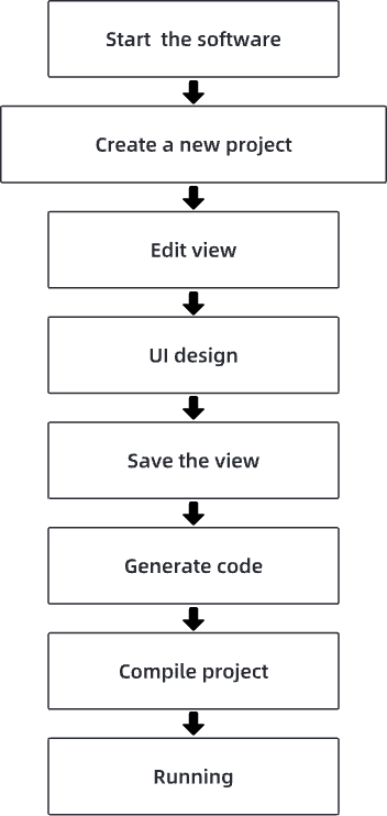
2.2. Launching the Software
Click on the "giraffe.exe" application to launching the software.
Main Menu:
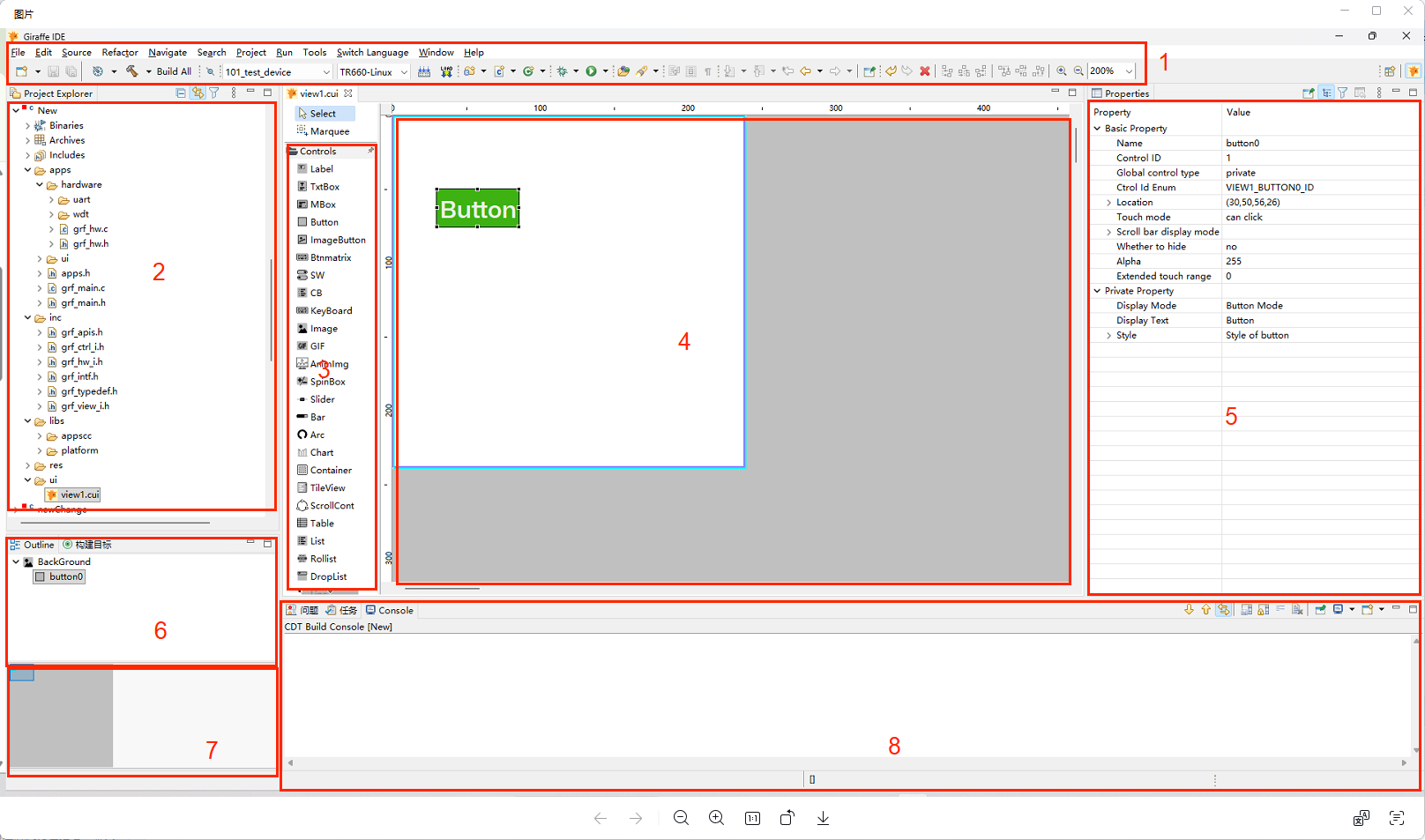
1. Menu Toolbar
Software function portal.
2. Project Structure Area
Project tree structure, clearly showing the hierarchy of the project structure.
3. Control Area
A collection of controls required for UI design. When creating controls, you can directly drag and drop them from the control area to the view margin to generate controls, and then click Save to automatically generate the code. You can view the code by right-clicking on the view margin area and selecting Jump to Control Events to see the relevant control event code for the current page. After saving the generated code, right-click on the project folder in the project structure area, select Build Project, Run as - Run Local Application to run the simulation window.
4. View UI Design Area
The effective area for UI design, you can drag and drop controls to this area by mouse, when dragging controls for UI design, you can directly drag and drop from the control area to the UI blank space to generate controls, or directly drag and drop to the already existing controls to form nested relationships.
When the view area is selected by the mouse, the UI design area can be scaled by ctrl+mouse wheel
5. Control Parameters Area
Set the parameters of the selected control in this area after mouse click to select the control
6. Current View Outline
The outline of the current design view is arranged to show all controls in the current view and the relationship between controls. When you select a control with the mouse in the outline, the view UI design area is also selected accordingly.
When you drag and drop a control in the outline, you can change the order of the controls or change the nesting relationships of the controls. For example, drag a control inside another control, or drag a control out of its parent control to change the sibling relationship.
The order of controls in the outline is by default in the order in which they are created, with higher priority being given to the controls further down the outline.
7. View Thumbnails
Thumbnails of the current UI design area
8. Console
Print the project log and see the project status at a glance.
2.3. New Construction and Project Setup
2.3.1. Create a New Project
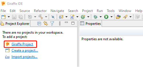
After launching the software, click on the Giraffe project,Note that the software installation path should avoid Chinese characters, spaces and special symbols.
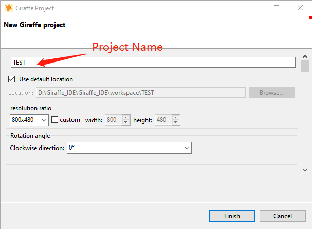
2.3.2. Configuring Project Information
Project name: the name of the current project to be created.
Save path: the path to save the file for the current project.Avoid Chinese characters, spaces, and special symbols in paths.
Platform: Select the running platform
Resolution: set the resolution of the view interface.
Rotation angle: the rotation angle of the current view, clockwise rotation.
2.3.3. Modifying project properties
Right-click the project folder and select Properties. Giraffe common properties: Giraffe Project propertiy, Display property, Hardware property.
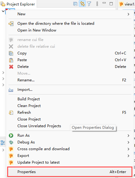
2.3.3.1. Giraffe Project propertiy
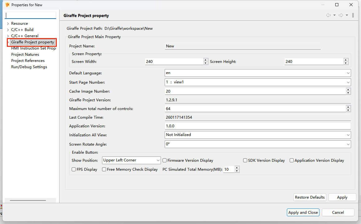
Project Name:Name of the project created by the user; it should conform to the C standard naming convention
Screen Property:Item resolution in pixels
Default:Default English; the default language can be modified after adding multi-language in the toolbar
Start Page Number:Initial page ID, users can select any page in the project as the initial page
Cache Image Number:Decode image resources in advance to effectively avoid lag during program operation
Giraffe Project Version:The current version of Giraffe used by the project
Maximum total number of controls:Maximum number of controls per view page, which can be changed according to the project needs
Last Compile time:The exact time the project was last compiled, including year, month, day, hour, minute, and second
Application Version:For customized application version
Initialize All Views:Load view resources in advance to effectively avoid lag during program operation
Screen Rotate Angle:Used to adjust the overall display direction of the project in the screen, without affecting the Giraffe simulation;Note that the logo image does not rotate with the boot up, the user needs to ../res/image file to change its orientation manually
Enable Button:The following six options can be checked to make it easier to view the relevant information; the location of the information can be selected from the upper left corner or the bottom of the center
Firmware Version Display:Automatically obtains and displays the firmware version in the current device
SDK Version Display:Giraffe UI library version
Application Version Display:Displays the version number of the app used by the project
FPS Display:Real-time display of current refresh frame rate
Free Memory Check Display:Users can dynamically adjust the resources used by the project according to the amount of memory remaining。for details,please refer to Chapter 8.1 of the Software API
Simulated PC Total Memory (MB):Allows you to simulate and set the total memory size of the PC (in MB)
2.3.3.1. Display property
Display Property for setting the standby protection function. This function contains three states, Original Page → Standby Page → Screen Off.
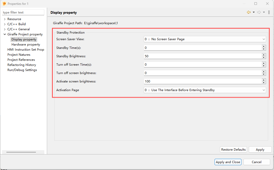
Screen Saver View:Standby page; users can select any view in the program
Standby Time:Time required to enter the standby page, in seconds
Standby Brightness:Display brightness of the standby page
Turn off Screen Time:Time from standby page to screen off state, in seconds
Turn off Screen Brightness:Display Brightness with Screen Off
Activate Screen Brightness:Display brightness when exiting standby protection and the screen is reactivated
Activate Page: Users can return to the page before standby or set any other view page
- Activation method after screen standby:1. TP Touch 2. API Function (The communication interface can receive external commands to call the API, which activates the screen)
2.3.3.1. Hardware property
Hardware properties contain three modules: Display Parameters, Prompt Sound, and Touch Configuration.
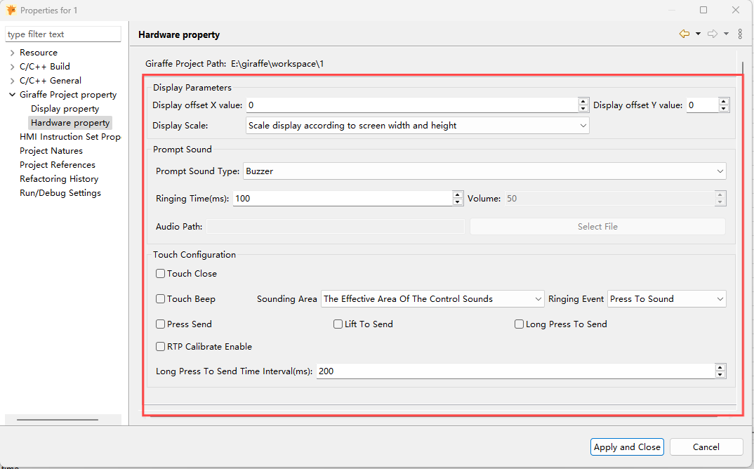
Display offset value:The offset value is the value required to interpolate the screen black; please refer to Chapter 8.7 of the Software API
Display Scale:Two display modes available:
Scale display according to the screen width and height:Adaptive scaling of the project size to ensure that the project page is fully displayed on the monitorAccording to the width and height of the project, display in equal proportions:If the width and height of the project are both less than or equal to the screen resolution, the project will be displayed in its own size without scaling
Prompt Sound Type:Works with Touch Configuration to call a buzzer when touched, or to call a user audio file
Ringing Time:Buzzer ringing time;If the prompt sound is a buzzer, users can set the ringing time as needed, unit: ms
Audio Path:Audio file path;If the prompt sound is audio, users can import the audio file by themsleves
Volume:If the prompt sound is a buzzer, the volume is fixed 50; or an audio file, users can set its volume level
Touch Close:Turn off the touch; the screen touch function will be disabled
Touch Beep:Used to set whether or not the buzzer sounds when the users touch the screen
Sounding Area:Sounding area optional:
The Effective Area Of The Control Sounds:The buzzer sounds only when users touch the area where the touchable control is located(If the control is touch-prohibited, it will not beep)Sound in Any Area:Beeps when any area is touched
Press Send:Send touch coordinates using the 04 01 instruction of the system instruction (B1) in the Giraffe Instruction Set ; three sending modes are available: press to send, lift to send, long press to send;the long press send event interval can be set by yourself, the unit ms
Ringing Event:Buzzer sound event optional:
Press to Sound:Buzzer sounds when touch is pressedLift then sound:Buzzer sounds when touch is lifted
RTP Calibration:After checking the box, click the invalid area (no control or control is not touchable) 20 times continuously within 5s to re-enter the calibration program
2.4. Editing a View
2.4.1. Creating a new view
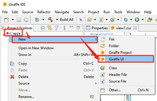
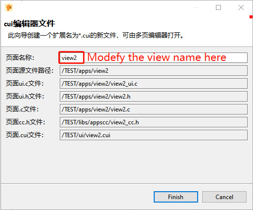
When the new project is completed, a starting view page, view1, is created and opened by default (and can be modified).When you want to create another view, right click on the project folder, select new->Giraffe UI page, the default name of the new view page is view2 (can be modified), click finish to complete the creation, the default jump to the new view after successful creation.
The name of the view is modified and the names of other documents related to this view are automatically adapted to the changes.
Create a new view as shown.

2.4.2. Configuring View Parameters
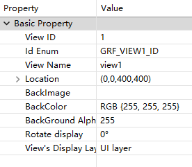
View Name: the name of the current view
View ID: ID of the current view
BackImage: add a background image for the view, the image supports both jpg and png formats, please refer to Chapter 8.3 of the Software API
BackColor: the color of the view's background
BackGround Alpha: the transparency of the view background, in the range [0-255] 0 is completely transparent 255 is completely opaque
Rotation Display: Rotate a single view by a specified angle (0°, 90°, 180°, 270°).
Note: This attribute is used to meet the requirements of both landscape and portrait display within the same project, supporting clockwise rotation at a specified angle for individual views.Rotation of a single layer is not supported. The final rotation angle is based on the UI layer; rotation of other layers follows the UI layer. If you need to achieve the overall project display effect of "using landscape screen in portrait mode" or "using portrait screen in landscape mode", please use the screen rotation angle in the project properties: this property will rotate all layers and content of the entire project.
- View's Display Layer Location: 4 types
GRF_LAYER_BG: Background Layer
GRF_LAYER_UI: UI layer.
GRF_LAYER_TOP: top layer.
GRF_LAYER_STATE: state layer.
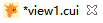
If you don't save the parameters, there will be an * in the view window.
Here BackColor(default value is (255,255,255)) is changed.
2.4.3. Preview View
Preview sequence: save->compile->run
Save:  (Ctrl+S)
 ->

Compile&Run
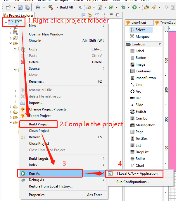
Or

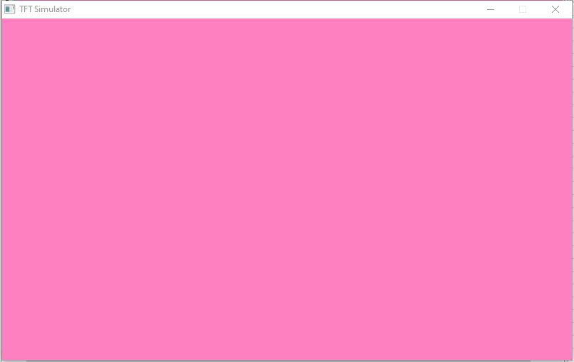
Once run, the live view will be displayed on simulator.
2.4.4. Delete View
Please follow the steps.
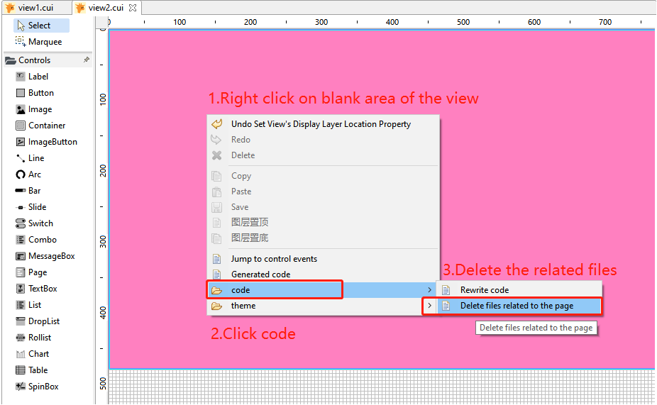
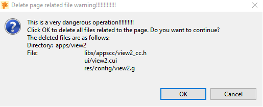
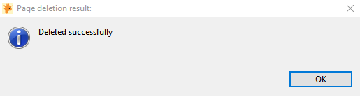
Delete effect compare:
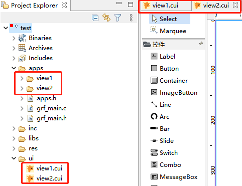
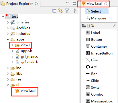
Left: Before Right: After
2.5. UI Design
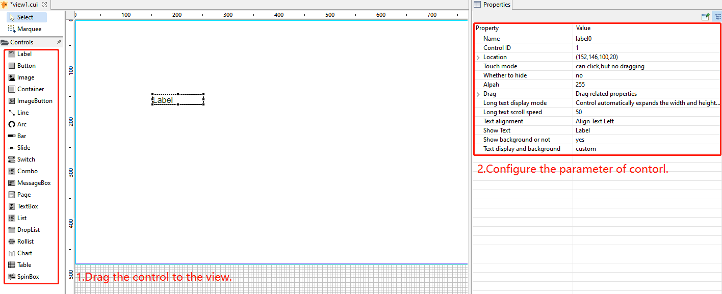
2.5.1. Call Controls
Once you have created the view, you can drag and drop controls from the controls area onto the view and then configure the control parameters for the view UI design.
2.5.2. Save View
After configuring the controls,you need to save the current view.
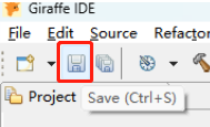
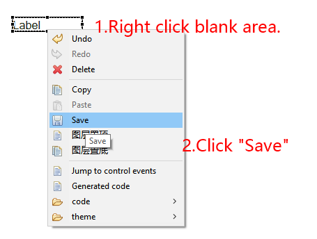
Save method:
Click the Save button directly (or Ctrl+S directly)
Click the right mouse button on the current view and select "Save"
2.5.3. Generating Code
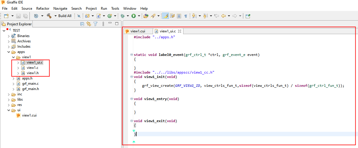
The generated code can be viewed in the project structure area, for example, the current code of view1
Open the apps folder in the project directory
click on the view1 folder
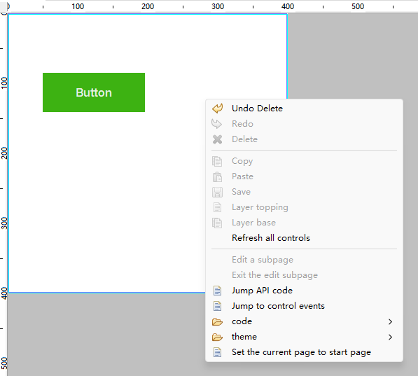
Double click on view1_ui.c to see the view code and control event functions in the view area. Or after generating the code, right click on the view and select jump to control events, you can also open.
Alternatively, right-click on the blank area of the view and select Jump to Control Events.(If you want to view the view API, select Jump to API from the right-click menu on the view interface to navigate to the API corresponding to the view.)
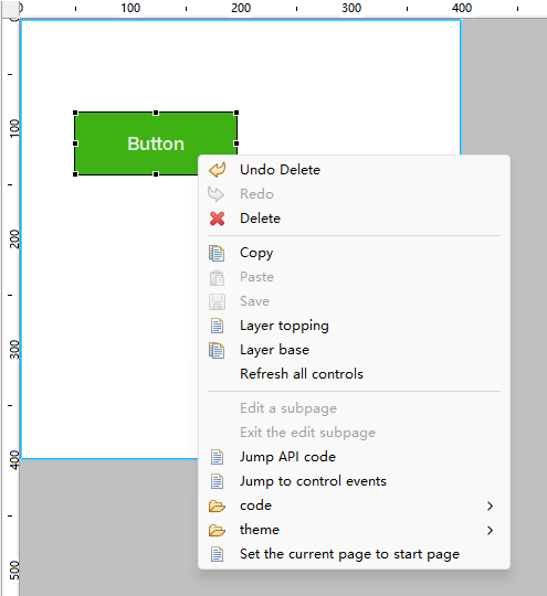
Or right-click the specified control and select Jump to Control Events to locate the control events corresponding to this control.(If you want to view the API corresponding to the control, right-click the specified control and select Jump to API to navigate to the API corresponding to this control.)
2.5.4. Compiling Project
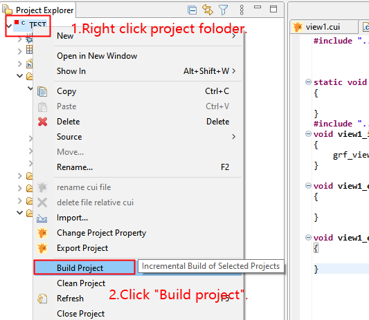
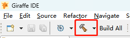
Or click the compile button on the toolbar.
2.5.5. Running
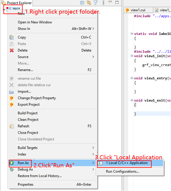
Or click the compile button on the toolbar.

Running effect:
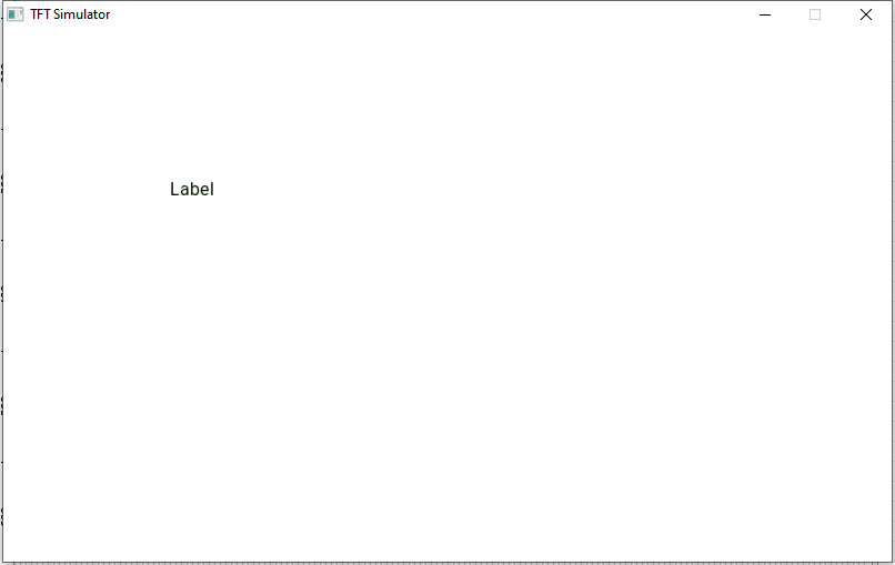
Summary of running flow:
Create control -> Save view -> Generate code -> Compile project -> Run
When you add a new control, you have to generate the code for the new control.
If you are only adjusting the current control (e.g. repositioning, resizing, adjusting parameters, etc.), because you have already generated the control code, and the adjustment only changes the internal parameters of the control, you do not need to generate the code again, just save it and run it.
2.6. Debugging
When a compile error is reported, you can select the debugging tool to view the error
Click on the Debug button in the toolbar and you will be in debugging mode after a few moments.

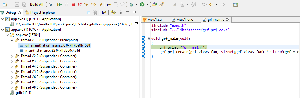
2.7. Opening an Existing Project
Open the software folder -> open the workspace folder -> select the existing project you want to open -> click to select the folder
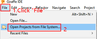
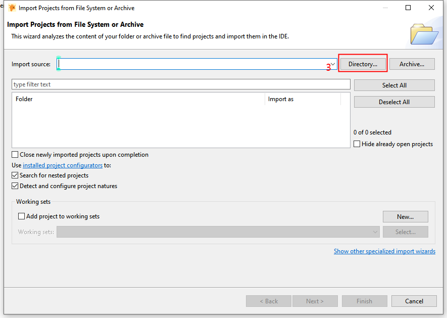
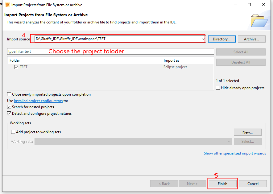
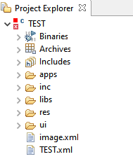
You can see that the project we want has been added to the project structure area and you can work on it afterwards.
2.8. Removing a project
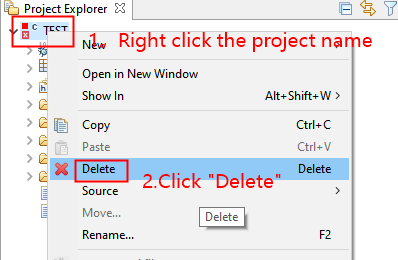
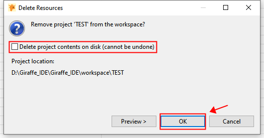
If you only want to remove the project and not delete the project file, please make sure you do not tick this box as it cannot be undone after you have ticked it, so please use caution.
2.9.Cross Compile and Download
2.9.1. Cross-compile
The cross-compilation build method is selected based on the screen driver IC model and the internal system. Currently, the following are supported: TR6-linux/TR540-RTOS/TR230-RTOS/TR240-RTOS.
There are two ways to choose for cross-compilation. Among them, the TR5 and TR6 series chips can be automatically recognized by the corresponding system when connected to a computer via USB, as shown in the following figure:
Method 1:
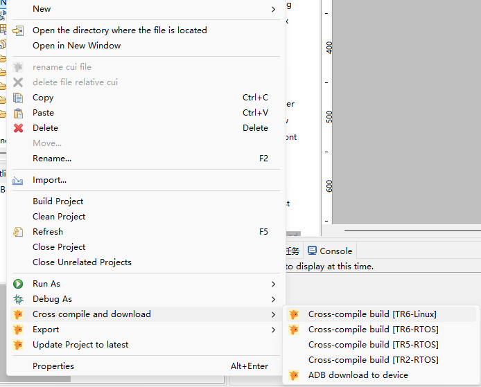
Method 2:
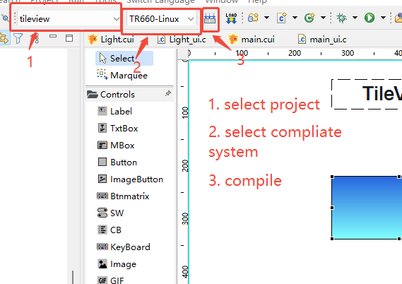
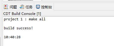
After successful cross-compilation, the console will display build success!
2.9.2. Download
Supported download methods vary by product model.TR660/TR670 supports USB cable, TF card and U disk download.TR540 supports USB cable and TF card download, do not support U disk.TR230/TR240 only support TF card download, USB cable or USB disk can not be supported.
1. Download via USB cable
IC Supported: TR670/TR660/TR540
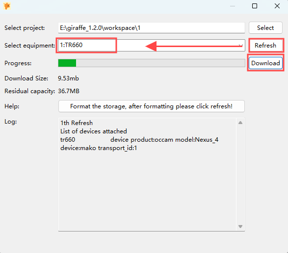
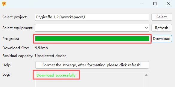
- USB cable to connect the device to the computer, open IDE, and select Download to device. After refreshing the device in the pop-up window , click Download. When the progress bar is 100%, Download Complete will be displayed and the device will automatically reboot to run the downloaded project.
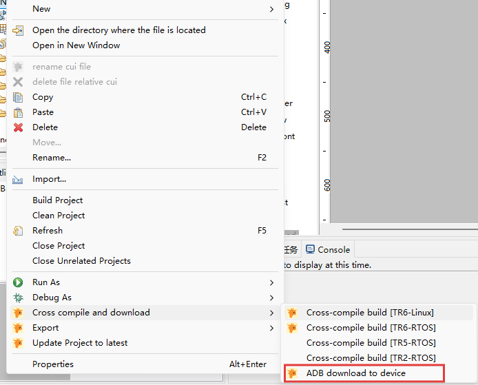
There are two ways to open the download window, as shown in the following figure: Method 1: Select the project, right-click, and choose Download to Device
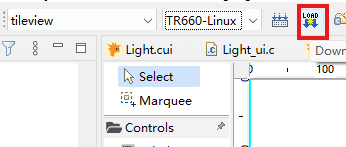
Click the "Download to Device` button on the toolbar
After the window is opened, click Refresh to obtain the device.
Click on Download --> Wait for the progress bar to complete
Note:
When using the TR5/TR6-RTOS, users may have a problem with the USB device being
unrecognized due to an error in the code that causes the power-up to crash.At this point, you can press and hold the "Download" button on the board to
restart the power, and then refresh the device to perform the download.
TR6-Linux don't support this way.
2. Download via TF card and U disk
Downloading from a USB flash drive is the same as downloading from a TF card, except that they have different transfer media.
IC that supports TF card download: TR670/TR660/TR540/TR230/TR240
IC that supports USB flash drive download: TR670/TR660
TF Card Requirements: FAT32 format, capacity less than 32GB
Select the corresponding IC model in the giraffe IDE to cross-compile build. Refer to section 2.9.1.
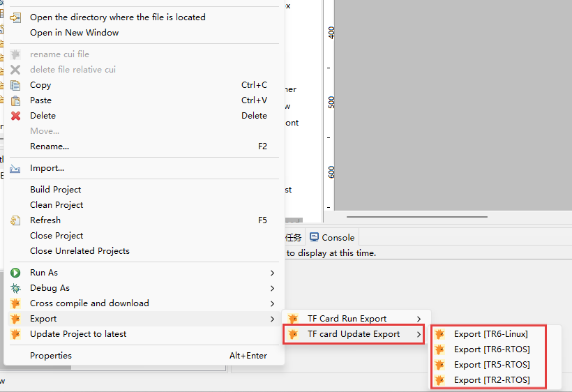
Right-click on the project and select Card Download Export to export a folder named
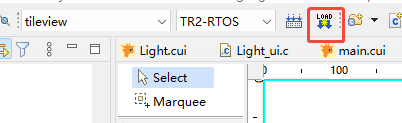
grf_update. Among them, TR2 can be optionally exported from the navigation bar.
TR2 can be selected to be exported in the navigation bar.
File Generation Notice:
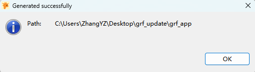
- Check whether the generated file is accurate
Different download files for different chips
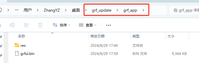
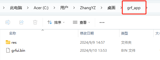
If the chip is TR660/TR670, select TR6. This will export the folder grf_update/grf_app, containing the files res and grfui.bin. The document nesting relationship is shown below.
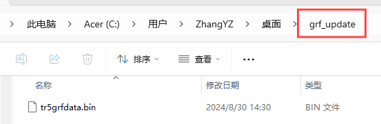
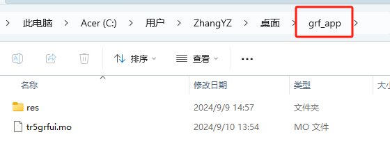
If the chip is TR540, select TR5, and the foldergrf_update will be exported. There is a file named tr5grfdata.bin in the folder.
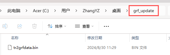
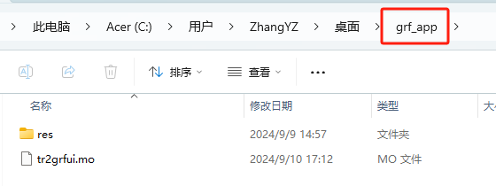
If the chip is TR230/TR240, select TR2, the grf_update folder has a file named tr2grfdata.bin in it.
Put the
grf_updatefolder directly on the TF cardInsert the TF card into the device and restart the power supply, then wait for reading UI. When the progress value is 100%, remove the TF card and restart the power supply again, then the project upgrade is successful.
2.10. TF Card Run Export
The executable program can be imported into the TF card and run directly, which can reduce the download time and speed up the debugging process. It is also possible to temporarily rule out the problem that the on-board flash is too small to be executed, and then reduce the resource capacity of the whole project after the debugging of all the functions is completed.
2.10.1
1. Windows
The Windows side can be used as a showcase, and you can directly send the customer's exported executable package for display, without sending the IDE and all project source code.
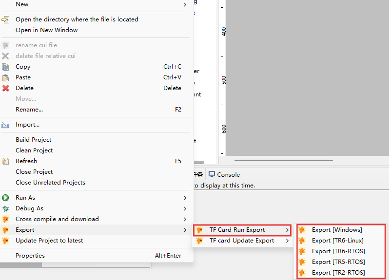
This option is used to view the running status of the project on the computer.
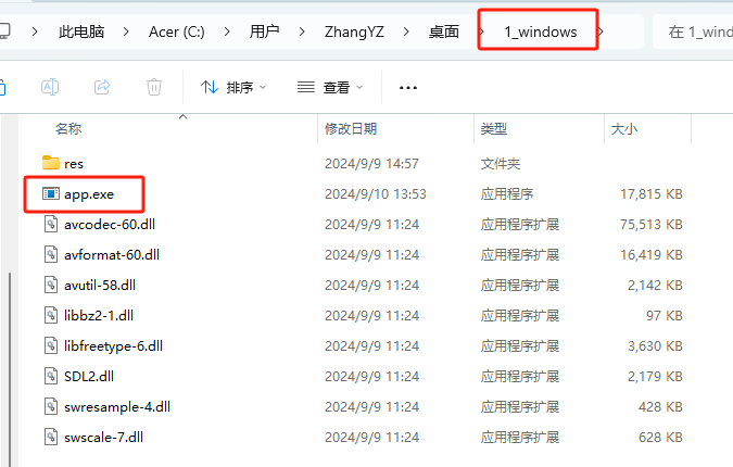
- Select Windows, the export name is
xxx_windowsfolder, xxx is the name of the current exported project. Double-click theapp.exefile to run the project interface directly to see the effect.
2. TR6/TR5/TR2
- Select TR6/TR5/TR2 and export a folder named
grf_app. Place thegrf_appfolder in the TF card, insert the device and reboot the power and wait for the UI to be read. Power up will run the card program directly.
[TR6-Linux Export File]
[TR5-RTOS Export File]
[TR2-RTOS Export File]
2.11. Burn Firmware
The firmware has been pre-programmed at the factory of our company. It does not require users to re-program it by default. Only when our company informs that the firmware needs to be upgraded to add new functions does it need to be updated. For the first use, you can temporarily ignore it.
Due to different product models, the firmware burning methods are different.
TR660/TR670/TR540 use the Giraffe firmware burning tool or TF card, TR230/TR240 only support TF card to burn firmware.
2.11.1. Giraffe Firmware Burning Tool( TR660/TR670/TR540 )
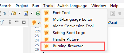
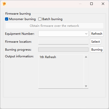
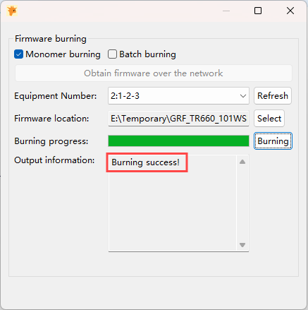
- Find the
Downloadbutton on the circuit board after connecting the device to the computer, press it down without lifting, at this time, restart the power supply, then release theDownloadbutton. As soon as you click onRefresh, the recognised device number will be displayed.
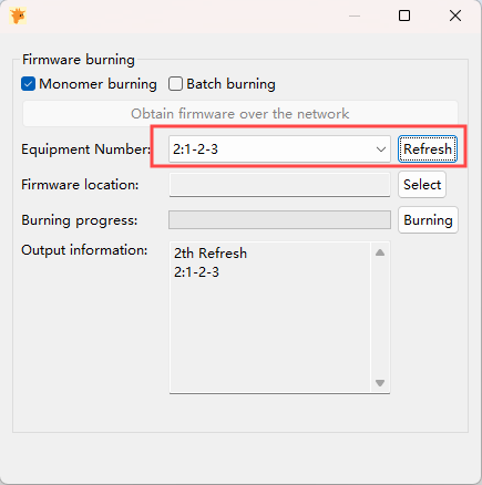
- If there is a
Resetbutton on the circuit board, pressing Reset and restarting the power supply have the same function.
- Select the firmware corresponding to the screen
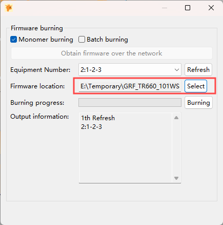
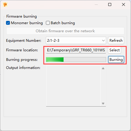
4. Click Burn
After Burning Success!, the TDO logo will be displayed in the centre of the screen, and you can download any project you want.
2.11.2. TF Card Firmware Burning( TR230/TR240 )
- For TR230/TR240 series products,
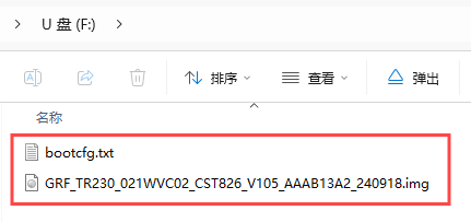
xxxxx.imgandbootcfg.txtfiles are needed to burn firmware, which can be placed directly in the root directory of TF card.
- If you receive a
.txtfile with the same name as the.imgfile, manually change its name tobootcfg.txt; the figure shows an example.
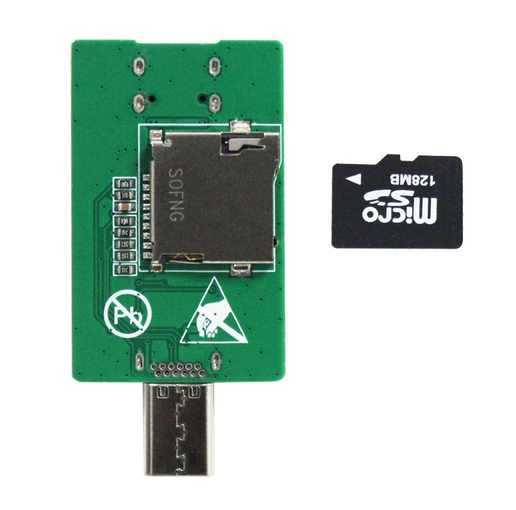
- Insert the TF card directly into the card slot of the serial screen, or insert it into the downloader (as shown in the figure) and then connect the serial screen;
Restart the power supply, the indicator light blinks rapidly to indicate that burning is in progress, and the blinking speed will slow down significantly after the burning is completed.
Pull out the TF card, restart the power, the screen will show TDO blue logo, at this time you can download any project.
2.12. Common Issues
2.12.1 Method of Using Win Virtual Serial Port
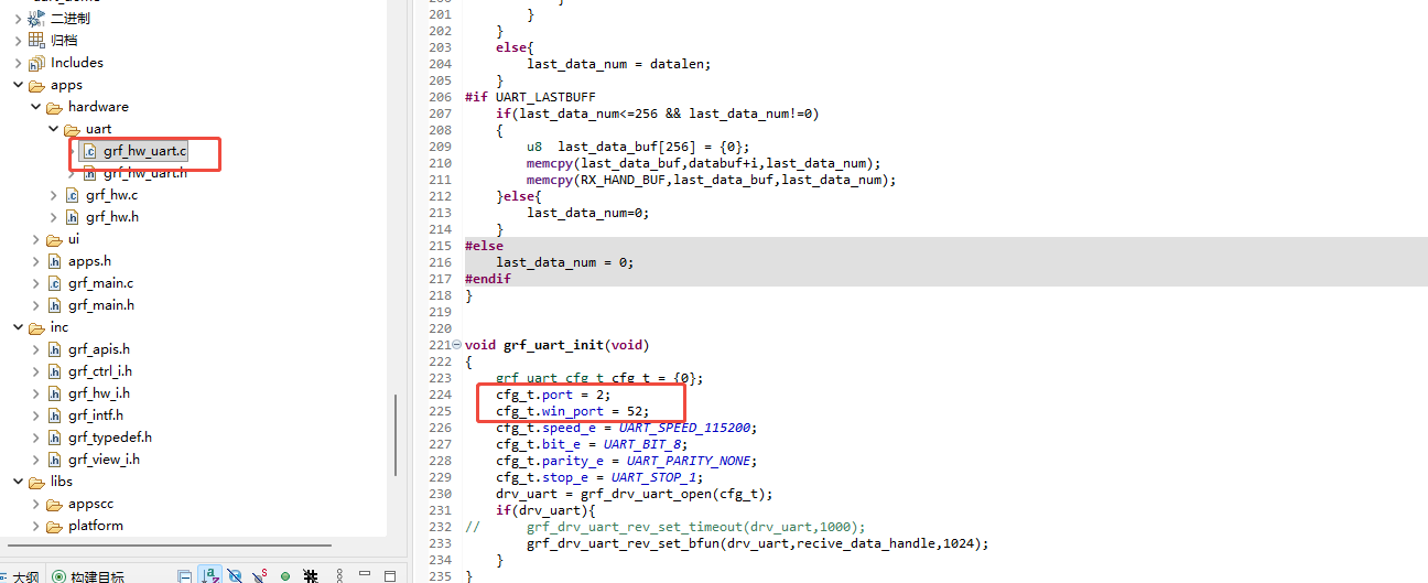
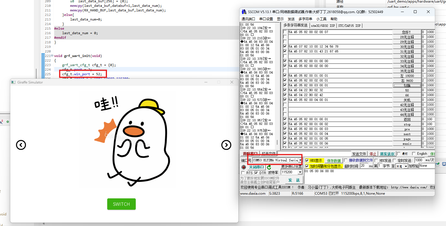
In the serial port initialization function of the uart folder, you will see the following two serial port configurations. port is the actual serial port configuration port number, and the win_port is the virtual serial port configuration port number. When debugging the communication of the serial port screen, directly call the virtual serial port and use the serial port debugging software to simulate the communication between the serial port screen and the client host, so as to quickly verify the program logic and save debugging time.
- Configure virtual serial ports
Use the VSPD virtual serial port software to map out two virtual serial ports and connect them together. The methods for obtaining and using the VSPD software can be found by yourself through online search.
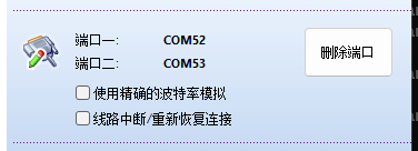
win_portconnects to a virtual port, while the serial port assistant software connects to another port, enabling the simulation of serial port communication between the screen and the client host.
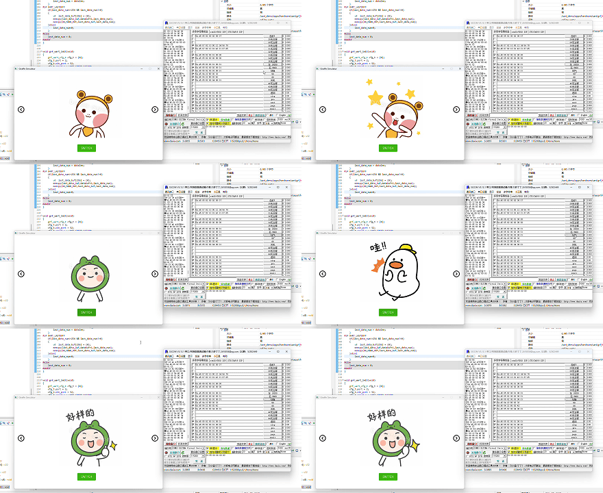
- The running effect is as follows
2.12.2 Differences between Private Controls and Public Controls
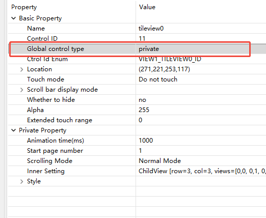
In the properties on the right panel of a control, the Global control type option can be set to Private or Public. The differences between the two are as follows:
Public: Accessible across views and valid throughout the entire project.
By default, global controls are only loaded into memory when their display is switched to, and subsequent accesses read directly from memory; they are not released when exiting the view. If there is a need to access a control before it is displayed, you can call the
grf_view_loadfunction in thegrf_mainfunction to load the global controls of that view into memory. You can also modify the project propertyInitialize all views on power-up, but this will slow down the power-up startup time.Private: Only valid for access when the current view is displayed, and released after switching views.
3. FAQ
3.1. Can't find debug button/option

Try clicking on the UI designer and debug keys in the top right corner of the software interface, then click back and forth to switch between them and the debug button/option will appear.
3.2. How to update the software
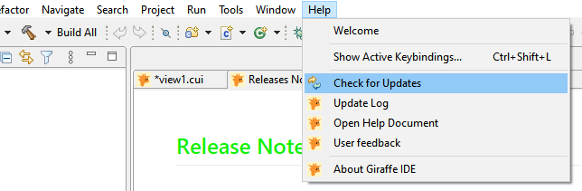
Find Help->Check for updates in the main menu bar of the software interface and double click on it.
The software will automatically link to the update URL (make sure your network is available) to load the update check and the following window will pop up
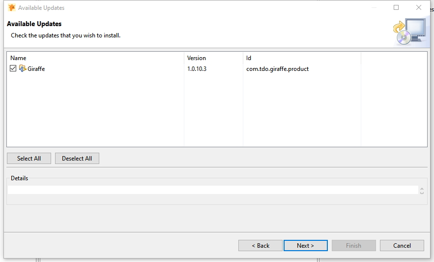
Check the version you want and click Next to download the update automatically.
3.3 Host Computer Cannot Recognize the Device
3.3.1 Problem Symptom
During project update, in the operation interface after cross-compiling and clicking Download to Device, after refreshing multiple times, the log only shows “List of devices attached” and the device list is empty. The target device cannot be selected or connected.
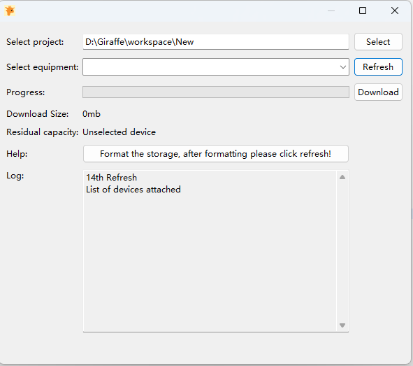
Under normal conditions, after the device is properly connected and recognized, you will see the following features on the interface:
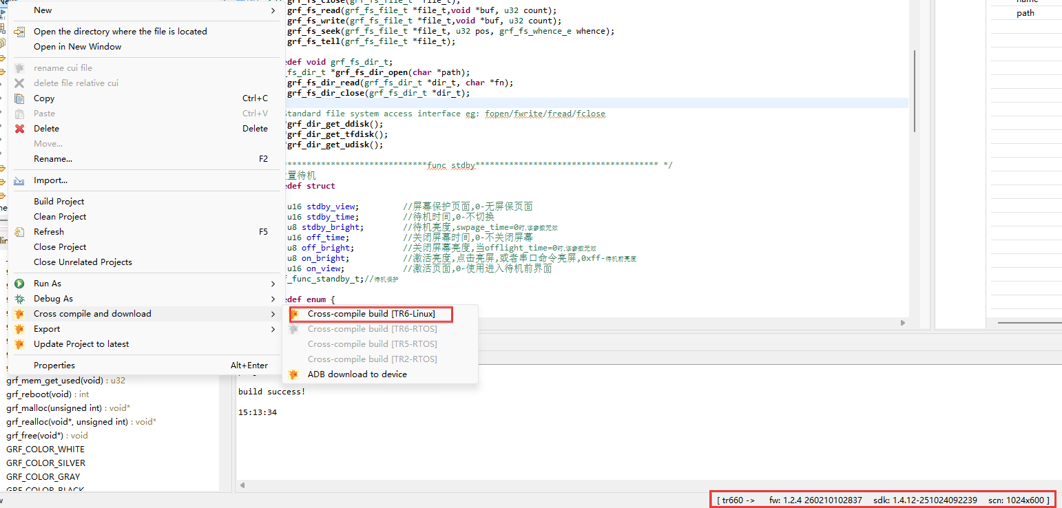
In the Cross Compile & Download submenu, only cross-compile build options that fully match the main controller and system of the currently connected device will be displayed. Incompatible options will be unavailable.
In the status bar below the console, detailed device information will be shown automatically, including:
- TR660: Main controller model
- fw: Firmware version
- sdk: Giraffe UI library version
- scn: Screen resolution
3.3.2 Possible Causes and Troubleshooting Steps
- Physical connection issue
Cause: Damaged or loose USB data cable; or use of a charge-only cable that does not support data transfer.
Troubleshooting steps: Replace with a USB cable that supports data transfer. Reconnect the device and the computer. Check if the USB port on the device side is loose or damaged. Unplug and reconnect to ensure a good connection. Check if the power indicator is on to confirm the device is powered normally.
- Driver issue
Cause: The device USB driver is not installed or not installed correctly on the computer.
Troubleshooting steps: Open Device Manager on the computer (Right-click This PC → Manage → Device Manager). Check for new devices under Universal Serial Bus controllers or Other devices.
Under normal conditions, shortly after connecting the device to the computer, FunctionFS gadget(adb) or ADB Interface will appear.
As shown in the figure below:
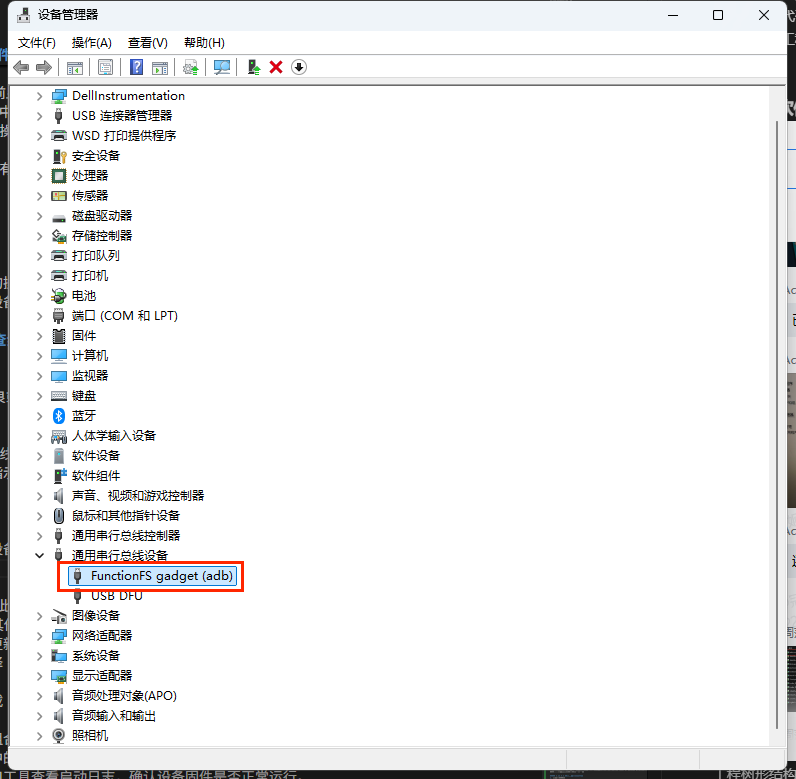
If there is an unknown device or a device with a yellow exclamation mark, right-click and select Update driver, then install it by pointing to the path where the driver files are located.